tisdag 13 oktober 2015

The Prototype

After much work, we are finally ready with the prototype!

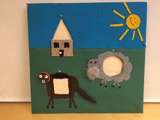
The already existing house has got company from two animals, a horse and a sheep. We chose to do the horse in some kind of leather to make it more attractive to touch. Furthermore, one addition to make the wall more playful is the head of the horse. A child kan spin it so the mouth and eyes roll in a funny way. The sheep has got a beard and the horse a tail which gives the interaction by feeling an extra touch. See following picture:

The prototype

We also managed to get all the LED's to work combined with the speaker. So now a LED will be lit up over a hole and a sound matching the animal and door plays when a block is identified.

Changes in design

From the beginning of the project the idea was to cover the wooden panel with a printed picture of a farm. But after some discussion in the group we realized that the playing experience wouldn’t be as pleasant as if we used fabric.

To start with, we chose to use padding all over the wooden panel to make the activity wall softer and more comfortable when the child plays. The main idea with the padding was to get rid of the feeling that the toy is completely made of wood.

Furthermore, to create the grass on the farm we chose green fabric and to represent the sky we used blue fabric. But when we created the house on the farm, we chose a different type of material. We chose to create the house with carpet, this creates the opportunity for the child to interact with the wall inform of feeling and touch. The child can feel that there is a house on the wall and that it doesn’t feel the same as the sky or the grass. An extra addition to the design is the sun you see in the first picture. We strived for a more cheerful experience for the kid that is playing.


On the back of the wooden panel we drilled four “legs” that raise the toy from the ground. We did this due to the fact that we wanted to make sure that the Arduino board and the speaker fits on the back. Also we decided to put squared plywood segments to work as resistance for our blocks and so we can put the RFID-readers.


Moreover, when it comes to the wooden geometrical blocks we made sure that we sanded them very carefully to make sure that we minimize the risk that the child don’t get hurt and that the surface feel smooth and nice.


To conclude this session, we can say that the problems we encountered were that it wasn’t easy to glue the fabric on the padding. The hot glue melted the padding and made it more difficult to attach the fabric.


tisdag 6 oktober 2015

Platform 5/10

At Monday 5/10, we had our platform good functioning will some design corrections needed to be made. 

Before the presentation we worked really hard to find a solution to have 3 RFID-readers to work. We realized that we don't need the RFID-readers to read simultaneously, just one at a time. 

To highlight the game again:
A player starts the game and take a seat in front of the wall. In front of the wall, three shapes should be placed: triangle, circle and rectangle. Each of this shapes got an matching hole in the wall. When the game starts, one of the holes will light up, the child now need to chose the right shape and place it against the hole. If the right shape is in place in time (some time limitation will be needed), the player gets one point, indicated on the top by a LED. The next shape now lights up and the procedure is the same. For each rond that is succeed, the time limit will be shorter. 

Back to the topic. As described above, we just need one RFID-reader to search at a time. After playing with the example code that was found on the RFID-readers website, in combination of searching a solution online we manage to find a solution. 

The pin RST, MOSI, MISO, SCK could be shared across the three readers. Only the SDA pin was needed to be unique. See scheme below. The pins was first defined and then we created three instances of the readers by "MFRC522 mfrc522(SS_PIN, RST_PIN);" for example for the first pin. Then we initialized the instanced by for example: "mfrc522.PCD_Init();"

 /*
 * Pin layout
 * --------------------------
 * MFRC522    |  Arduino Uno Pin
 * --------------------------
 * RST              |  7/ICSP-5 (shared)                   
 * MOSI           |  ICSP-4   (shared)  
 * MISO           |  ICSP-1   (shared) 
 * SCK             |  ICSP-3   (shared) 
 * SDA1 (SS)   |  9        (reader 1)
 * SDA2 (SS)   |  10      (reader 2)
 * SDA3 (SS)   |  6       (reader 3)
 */

The program (beta-version) was then structured to search with the reader 1 and at the same time light a LED to indicate what RFID-reader was used. After 5 seconds of searching, the program switched to the next RFID-reader and LED. If the right shape* was held at the right hole, an green LED lighted up to indicate the success. 

* The shape was at this phase created by a wood part with a RFID-tag taped to it. In a later phase this will be clad in fabric, probably in some sort of animal pattern. 
Playing with RFID modules in lab

[DELAYED POST]

We started to work with the RFID-reader. This wasn't a dance on red roses of course. At first we used some sample code found on X. That worked OK which made us very happy. The next step was to write to the RFID-tag. To find a sample code for this was way harder. After some searching we found some sample code that had worked for some other people on Internet. The reader detected the tag but only had possible to read some of the blocks, the rest we got ERROR. This error was also given when trying to write to the tag. We tried to troubleshoot but didn't find a solution. We discussed with Mattias what might could be wrong. Conclusion was that maybe these tags wasn't writable, even through it would be strange. In the sample code there was multiple examples of writing and all got the same problem. 

Then suddenly we hold the tag against the reader a little longer. Now the reader could access all the blocks. Suddenly we understood! The problem was that the code did so much things a part from just reading that it needed more time. Also when writing to the tag we needed to hold the tag against the reader during the whole process. This was the solution for us. 


A decision that was made during the lab was that we will setup the tags using only the UID of the tag. For example the UID 511 = triangle. This was decided to avoid reading from different blocks which we saw took some time and might cause problem in future.

An issue that we are heading to in future is how to use several RFID-readers in parallel, or rather how should we get three RFID-readers to detect chips with only one Arudino? We have a limited amount of pins and each RFID-reader uses approx. 6 input/outputs. Hopefully some of the inputs/outputs can be reused.

It will be exiting to see how we will manage to work with it. Stay tuned!